The AX7219 IS an integrated serial I/O COMMon-cathode display driver that connects a microprocessor to an 8-digit, 7-segment digital LED display, as well as a line graph display or 64 individual leds. It includes an on-chip type B BCD encoder, multipath scan loop, segment word driver, and an 8 by 8 static RAM to store each piece of data. Only one external register is used to set the segment current of each LED.
A convenient four - wire serial interface can be connected to all general - purpose microprocessors. Each data can be addressed at update time without the need to rewrite all the displays. The MAX7219 also allows the user to choose to encode or not encode each piece of data.
The entire device includes A 150-μA low-power off mode, analog and digital brightness controls, A scan limit register that allows the user to display 1-8 bits of data, and A detection mode that allows all leds to glow.
Only 3 I/O ports are needed to drive 1 dot matrix! No flicker when dot matrix display! Support for cascading!
Module parameters:
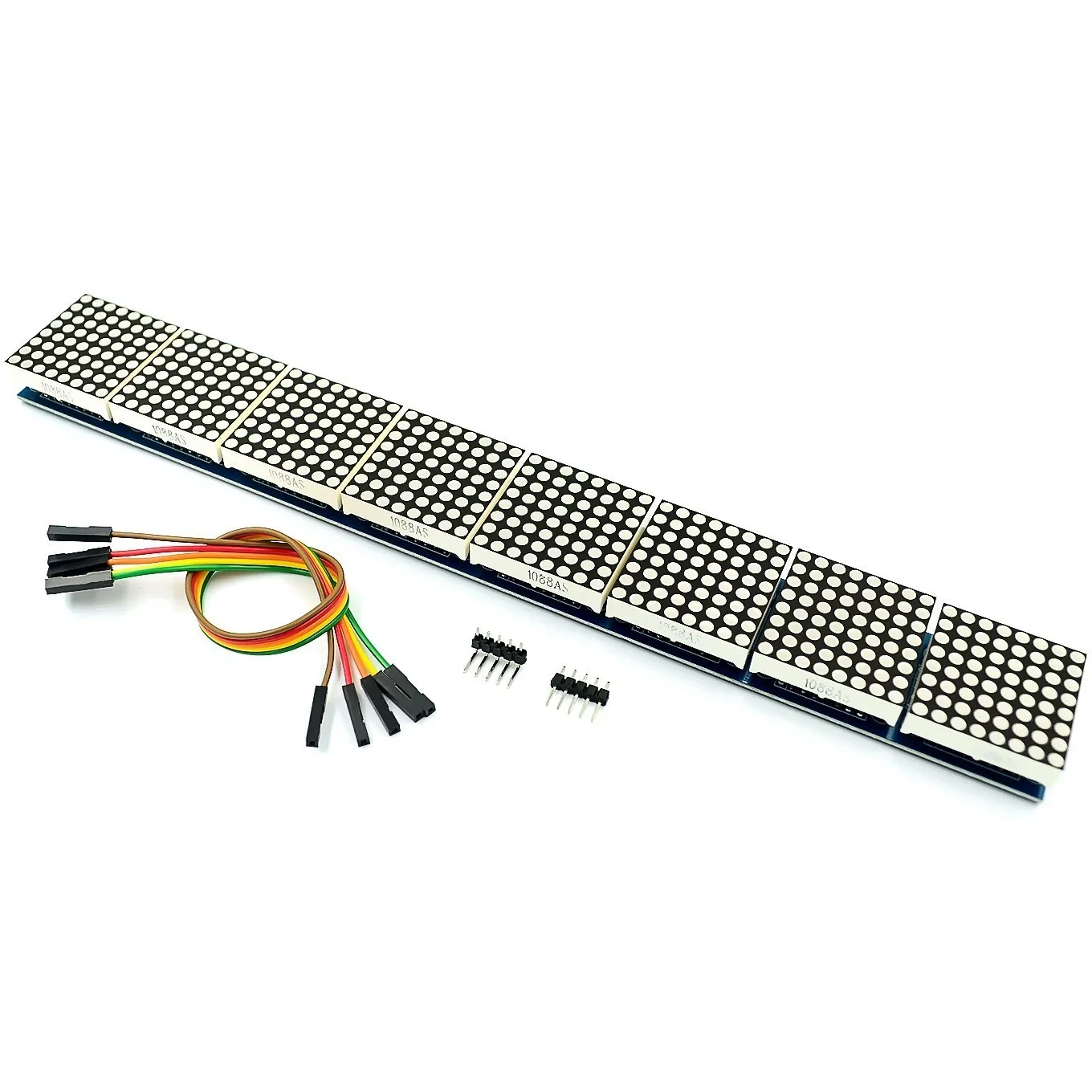
1. A single module can drive an 8*8 common negative lattice
2. Module operating voltage: 5V
3. Module size: length 26.5 cm X width 3.2 cm X height 1.3 cm
4. With 32 fixing screw holes, aperture 3mm
5. The module has input and output interfaces and supports the cascading of multiple modules
Wiring instructions:
1. The left side of the module is the input port, and the right side is the output port.
2. To control a single module, connect input ports only to the CPU
3. When multiple modules are cascaded, the input terminal of the first module is connected to the CPU, the output terminal is connected to the input terminal of the second module, the output terminal of the second module is connected to the input terminal of the third module, and so on...
Take 51 microcontroller as an example:
The VCC - 5 v
GND to GND
DIN - P2.2
CS - P2.1
The CLK - P2.0
Delivery List:
1.MAX7219 lattice module in eight (finished product, with lattice, tested)
2.20CM Dupont line 5P
3. One pin for each 5P straight bend
 The MAX7219 is an integrated serial I/O common-cathode display driver that connects a microprocessor to an 8-digit, 7-segment digital LED display, as well as a line graph display or 64 individual leds. It includes an on-chip type B BCD encoder, multipath scan loop, segment word driver, and an 8 by 8 static RAM to store each piece of data. Only one external register is used to set the segment current of each LED.
A convenient four - wire serial interface can be connected to all general - purpose microprocessors. Each data can be addressed at update time without the need to rewrite all the displays. The MAX7219 also allows the user to choose to encode or not encode each piece of data.
The entire device includes A 150-μA low-power off mode, analog and digital brightness controls, A scan limit register that allows the user to display 1-8 bits of data, and A detection mode that allows all leds to glow.
Only 3 I/O ports are needed to drive 1 dot matrix! No flicker when dot matrix display! Support for cascading!
Module parameters:
1. A single module can drive an 8*8 common negative lattice
2. Module operating voltage: 5V
3. Module size: length 26.5 cm X width 6.4 cm X height 1.3 cm
4. With 64 fixing screw holes, aperture 3mm
5. The module has input and output interfaces and supports the cascading of multiple modules
Wiring instructions:
1. The left side of the module is the input port, and the right side is the output port.
2. To control a single module, connect input ports only to the CPU
3. When multiple modules are cascaded, the input terminal of the first module is connected to the CPU, the output terminal is connected to the input terminal of the second module, the output terminal of the second module is connected to the input terminal of the third module, and so on...
Take 51 microcontroller as an example:
The VCC - 5 v
GND to GND
DIN - P2.2
CS - P2.1
The CLK - P2.0
Delivery List:
1.MAX7219 2*8 lattice module
2.20CM Dupont line 5P
3. 2.54 5 p row needles


 배송기간
배송기간